Ever stared at two pieces of metal you need to join and wondered, "How much overlap is actually enough?" It’s a question that keeps fabricators up at night. Too little overlap, and your joint snaps under pressure. Too much, and you’re wasting expensive filler metal, time, and energy. It’s the classic engineering dilemma of finding that sweet spot. You want it just right. Not too short, not too long. Just right.
In the world of structural integrity, whether you’re reinforcing concrete with rebar or assembling delicate HVAC components, the lap length is the unsung hero. It’s the silent partner that holds everything together when the load hits. But here’s the thing: there isn’t one magic number that works for every situation. The rules change depending on whether you’re welding steel bars in a skyscraper or brazing copper tubes in a refrigeration unit. Getting it wrong isn’t just an aesthetic issue; it’s a safety hazard. So, let’s dive into the nitty-gritty of optimizing these connections without getting bogged down in overly complex jargon.
Understanding the Basics of Load Transfer
At its core, a lap joint is about transferring force from one piece of material to another. Think of it like a handshake. If you barely touch fingertips, the grip is weak. If you grab the whole arm, it’s awkward and unnecessary. You need enough surface area for the "handshake" to be firm. In welding and brazing, this surface area is created by overlapping the two base metals. The strength of the joint depends heavily on how well the filler material (the weld bead or braze alloy) bonds with that overlapping area.
For welded connections, especially in reinforced concrete structures, the goal is monolithic behavior. As noted by the Concrete Reinforcing Steel Institute (CRSI), properly designed splices are key to transmitting forces through the structure. When you weld rebars, you aren’t just sticking them together; you’re creating a continuous load path. If the lap is too short, the stress concentrates at the ends of the weld, leading to premature failure. It’s like trying to hold a heavy box with just your fingertips versus using your whole palm. The distribution of stress matters immensely.
Brazing works slightly differently but follows the same logic. Since brazing relies on capillary action to draw the filler metal into the joint, the gap between the parts and the length of the overlap are critical. Lucas Milhaupt, a leader in brazing solutions, emphasizes that lap joints typically provide greater bonding area than butt joints. This increased area allows for better stress distribution. However, if the lap is excessively long, the filler metal might not flow all the way to the center, leaving voids. These voids become weak points. So, understanding that balance between sufficient bonding area and effective filler flow is the first step toward optimization.
The Math Behind the Magic: Calculating Welded Lap Lengths
When it comes to welding, particularly in construction, codes and standards rule the day. You can’t just eyeball it. For reinforced concrete, the lap length is often dictated by the diameter of the bar and the type of stress it’s under (tension or compression). A common rule of thumb for lap welds in rebar is that the length should be around 1.3 times the diameter of the bar, though this can vary based on specific code requirements like those from ACI or local building regulations. For instance, if you’re working with a 20 mm rebar, a butt weld might equal the diameter (20 mm), but a lap weld needs more room to breathe and transfer that load effectively.
But why 1.3? Or whatever factor your local code specifies? It comes down to development length. This is the length required to fully develop the strength of the bar through bond stress. If the lap is shorter than the development length, the bar will slip before it reaches its yield strength. That’s a catastrophic failure mode we definitely want to avoid. Engineers use modifiers to adjust this length based on factors like concrete strength, bar coating (epoxy-coated bars need longer laps), and spacing. It’s a bit of a puzzle, but tools like the SkyCiv Lap Length Calculator have made it easier for professionals in 2026 to verify their manual calculations quickly.
Don’t forget about the quality of the weld itself. A perfect lap length means nothing if the weld penetration is poor. The heat input, travel speed, and electrode angle all play a role. If you’re welding thick plates, you might need a longer lap to accommodate multiple passes or to reduce the stress concentration at the toe of the weld. It’s not just about the linear measurement; it’s about the volumetric integrity of the connection. Always double-check your calculations against the latest site practices and don’t rely solely on generic formulas. Context is king.
Optimizing Brazed Joints: Capillary Action and Stress
Brazing is a different beast. Here, we’re not melting the base metal. We’re melting a filler metal that has a lower melting point, letting it wick into the joint via capillary action. This process is sensitive. The optimal lap length for a brazed joint is often determined by the strength of the base metal versus the strength of the filler. A widely accepted guideline is that the lap length should be three times the thickness of the thinner member being joined. Why three? Because beyond that point, adding more length doesn’t significantly increase the joint’s strength. The base metal will fail before the braze does.
Let’s break that down. If you have a copper tube with a wall thickness of 1 mm, you’d aim for a lap length of about 3 mm inside the fitting. Going to 10 mm won’t make the joint three times stronger. In fact, it might make it weaker because it becomes harder to ensure the flux cleans the entire surface and the filler flows evenly. Trapped flux or air pockets in a long, narrow gap are common defects. These defects act as stress risers. When the system vibrates or undergoes thermal cycling, cracks start at these weak spots. So, more isn’t always better. It’s about efficiency.
Stress distribution is another key factor. In a lap joint, the stress isn’t uniform. It’s highest at the edges of the overlap and lowest in the middle. This is known as shear lag. By keeping the lap length optimized (around that 3x thickness mark), you ensure that the majority of the joint is working effectively. If the lap is too long, the center of the joint contributes very little to the overall strength, making it dead weight. This is crucial in industries like aerospace or automotive, where every gram counts. In 2026, with lightweight materials becoming more prevalent, optimizing this ratio is more important than ever.
Common Pitfalls and How to Avoid Them
One of the biggest mistakes folks make is ignoring surface preparation. You can have the perfect lap length calculated to the decimal, but if there’s oil, oxide, or dirt on the surface, the joint will fail. In welding, this leads to porosity and lack of fusion. In brazing, it prevents the filler from wetting the surface. Always clean your metals. Use stainless steel brushes, solvents, or mechanical abrasion. It sounds basic, but it’s the number one cause of joint failure in the field. Don’t skip this step. Ever.
Another pitfall is inconsistent fit-up. Gaps matter. In brazing, the ideal gap is usually between 0.002 and 0.005 inches. If the gap is too wide, capillary action breaks down. If it’s too tight, the filler can’t get in. For welding, excessive root gaps can lead to burn-through or excessive distortion. Use fixtures and jigs to hold your parts in place. Consistency is your friend. If you’re doing high-volume work, invest in good tooling. It pays for itself in reduced rework.
People also tend to overlook the effects of thermal expansion. Different metals expand at different rates when heated. If you’re joining dissimilar metals, a lap joint that looks perfect at room temperature might open up or close tightly when it’s hot. This can cause cracking during cooling. Account for this in your design. Sometimes, a slightly longer lap can help accommodate some movement, but often, selecting the right filler metal with compatible thermal properties is the better solution. Check the datasheets. They’re there for a reason.
Real-World Applications and Case Studies
Let’s look at a practical example. Imagine you’re fabricating a heat exchanger for a commercial HVAC system. You’re using copper tubes and brass fittings. The standard practice suggests a lap length of 3 times the tube wall thickness. If the wall is 0.8 mm, you’re looking at a 2.4 mm lap. In production, you might round this to 3 mm for ease of manufacturing and to provide a small safety margin. Tests show that this length provides full joint efficiency. Going to 6 mm would double the amount of braze alloy used and increase heating time, slowing down production without adding strength. That’s a direct cost saving.
Now, consider a civil engineering project. A bridge deck requires splicing #8 rebars (25 mm diameter) in a tension zone. According to ACI 318 code updates relevant in 2026, the development length might require a lap splice of 40 to 50 diameters depending on concrete strength and bar spacing. That’s over a meter of overlap! Clearly, welding or mechanical couplers might be preferred here to save space and congestion. But if welding is chosen, the weld length must be sufficient to develop the full yield strength of the bar. A partial weld won’t cut it. Engineers often use full-penetration groove welds or high-strength fillet welds with calculated lengths to ensure the splice performs as well as the continuous bar.
These examples highlight that "optimal" is context-dependent. In the HVAC case, optimal means cost-effective and sufficiently strong. In the bridge case, optimal means meeting strict safety codes and ensuring long-term durability under dynamic loads. There’s no one-size-fits-all. You have to look at the specific demands of the application. What is the load? Is it static or dynamic? What are the environmental conditions? Answering these questions guides your choice of lap length.
In 2026, technology has made our lives easier. We’re not just relying on slide rules and handbooks anymore. Digital calculators and simulation software allow us to model stress distributions in lap joints before we even strike an arc. Tools like the Wire Reinforcement Institute’s calculators or third-party apps can quickly determine prescriptive minimums. But remember, these are starting points. Engineering judgment is still required. Always verify against local codes. Regulations change, and your liability depends on compliance.
Visual inspection aids have also improved. High-resolution borescopes allow you to check the internal quality of brazed joints without destructive testing. For welds, ultrasonic testing can detect lack of fusion in lap joints that look fine on the surface. Using these non-destructive testing (NDT) methods helps validate that your chosen lap length is performing as expected. It builds confidence. If you’re consistently seeing defects at the ends of your laps, maybe you need to adjust your technique or slightly increase the length to move the stress concentration away from critical areas.
Training is another vital tool. The best calculation in the world won’t help if the welder or brazer doesn’t understand the why behind the numbers. Invest in training your team. Show them cross-sections of good and bad joints. Explain the concept of shear lag. When practitioners understand the mechanics, they take more pride in their work and pay attention to details like fit-up and cleanliness. It creates a culture of quality. And in the end, that’s what ensures safety and reliability.
Getting the lap length right is a blend of science, art, and experience. It’s about respecting the materials and the forces at play. Whether you’re welding massive steel girders or brazing tiny electronic components, the principles remain the same: ensure sufficient bonding area, distribute stress evenly, and avoid waste. By following code guidelines, understanding the underlying physics, and leveraging modern tools, you can create connections that are not only strong but also efficient.
Remember, there’s no shame in double-checking your work. In fact, it’s a sign of professionalism. Review your calculations. Inspect your joints. Ask questions. The field of joining technologies continues to evolve, with new alloys and techniques emerging regularly. Staying curious and informed is the best way to keep your skills sharp. So, the next time you’re faced with a lap joint, take a moment to think about the load path. Measure twice. Weld or braze once. And rest easy knowing you’ve built something that will last.
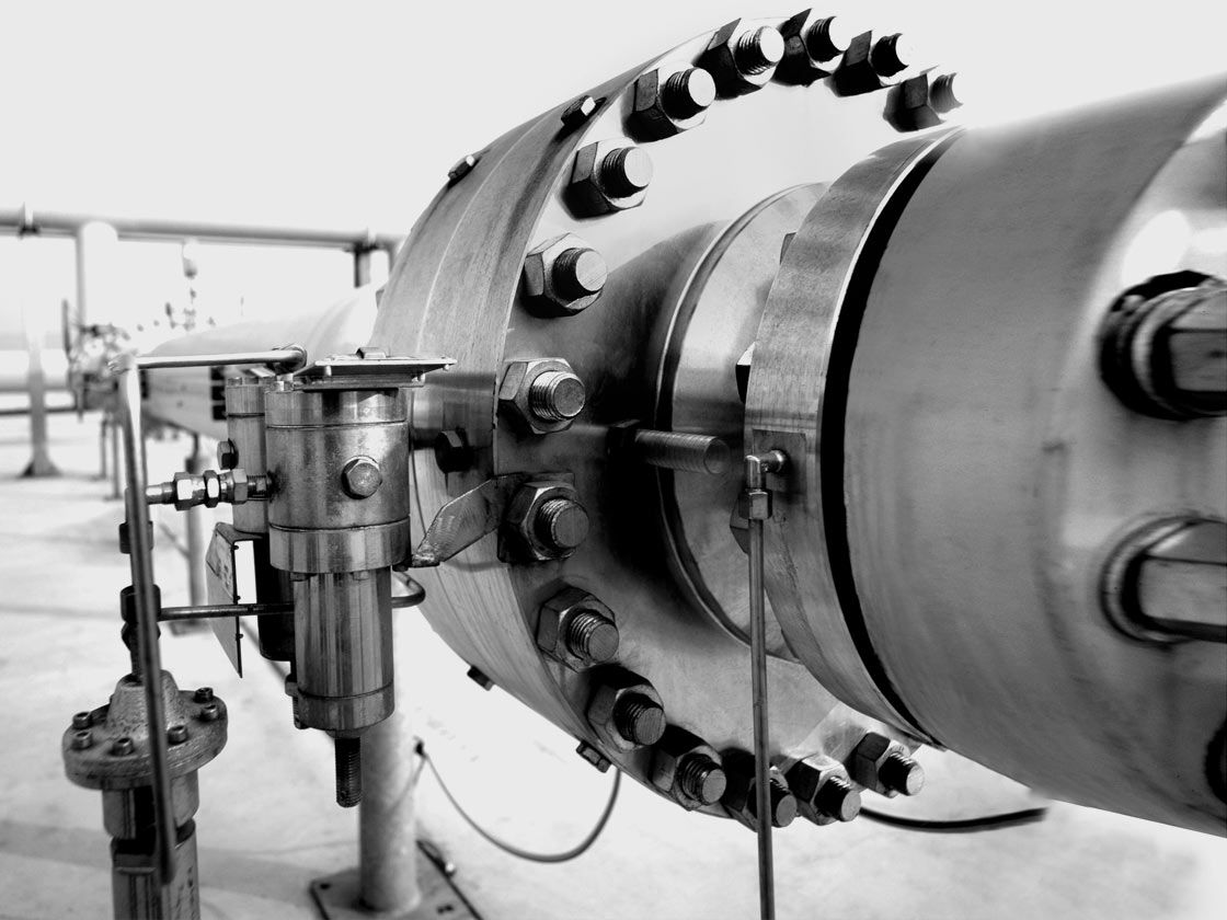
[sps_html tag=”img” src=”https://cdn.northcarolinafinearchitecture.com/2026/05/stop-treating-bolted-joints-differently-from-welded-joints-team-inc-throughout-stop-treating-lap-joints-like-butt-joints-and-avoid-catastrophic-failures.jpg” alt=”Stop Treating Bolted Joints Differently From Welded Joints | Team, Inc. throughout Stop treating lap joints like butt joints and avoid catastrophic failures” style=”width: 100%; height: auto;”]
[sps_html tag=”img” src=”https://cdn.northcarolinafinearchitecture.com/2026/05/different-types-of-welding-joints-butt-corner-lap-tee-edge-within-lap-joint-design.jpg” alt=”Different Types Of Welding Joints (Butt, Corner, Lap, Tee & Edge … within Lap Joint Design” style=”width: 100%; height: auto;”]
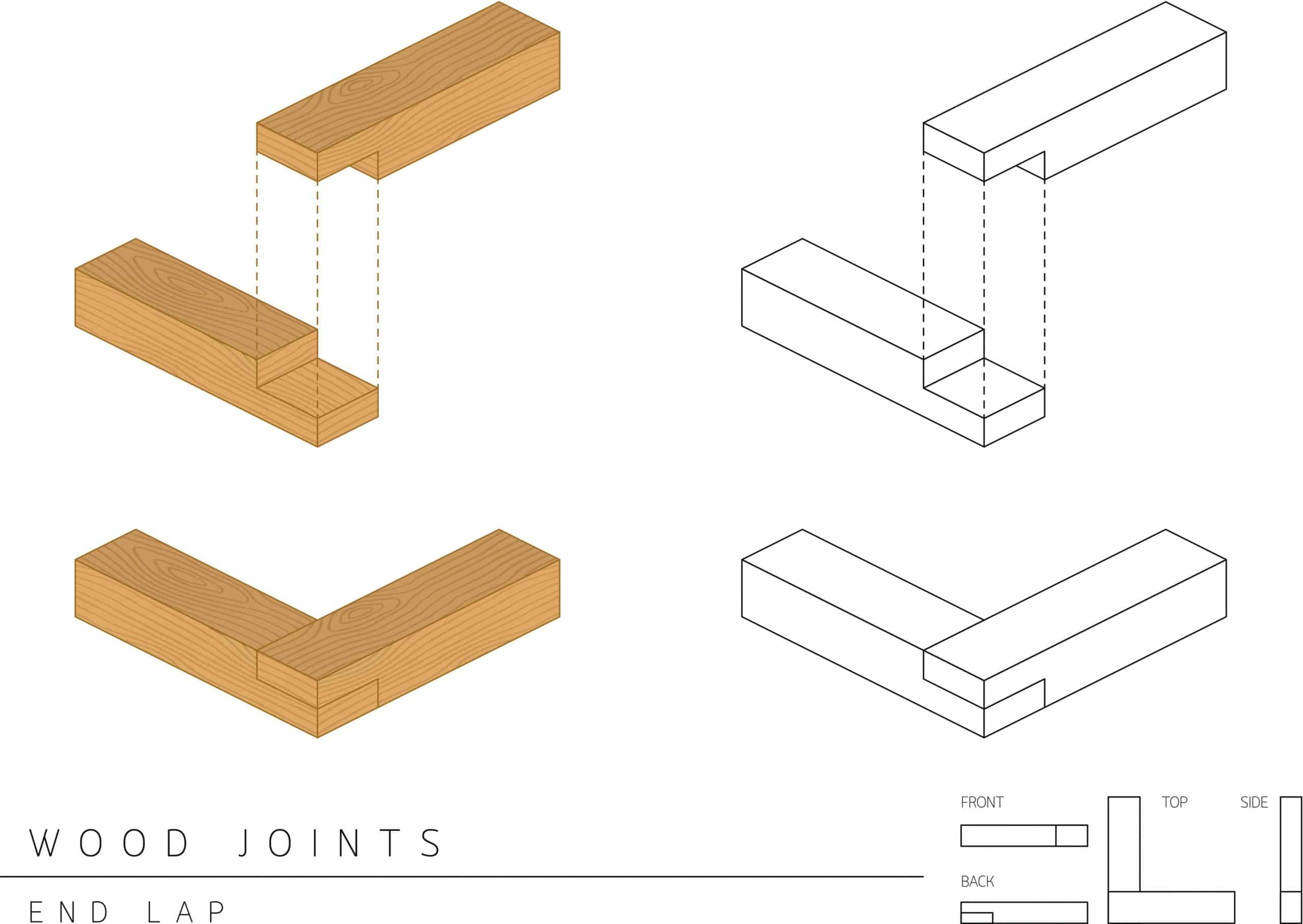
[sps_html tag=”img” src=”https://cdn.northcarolinafinearchitecture.com/2026/05/what-is-a-lap-joint-how-to-cut-a-lap-joint-within-stop-treating-lap-joints-like-butt-joints-and-avoid-catastrophic-failures.jpg” alt=”What Is A Lap Joint? How To Cut A Lap Joint within Stop treating lap joints like butt joints and avoid catastrophic failures” style=”width: 100%; height: auto;”]
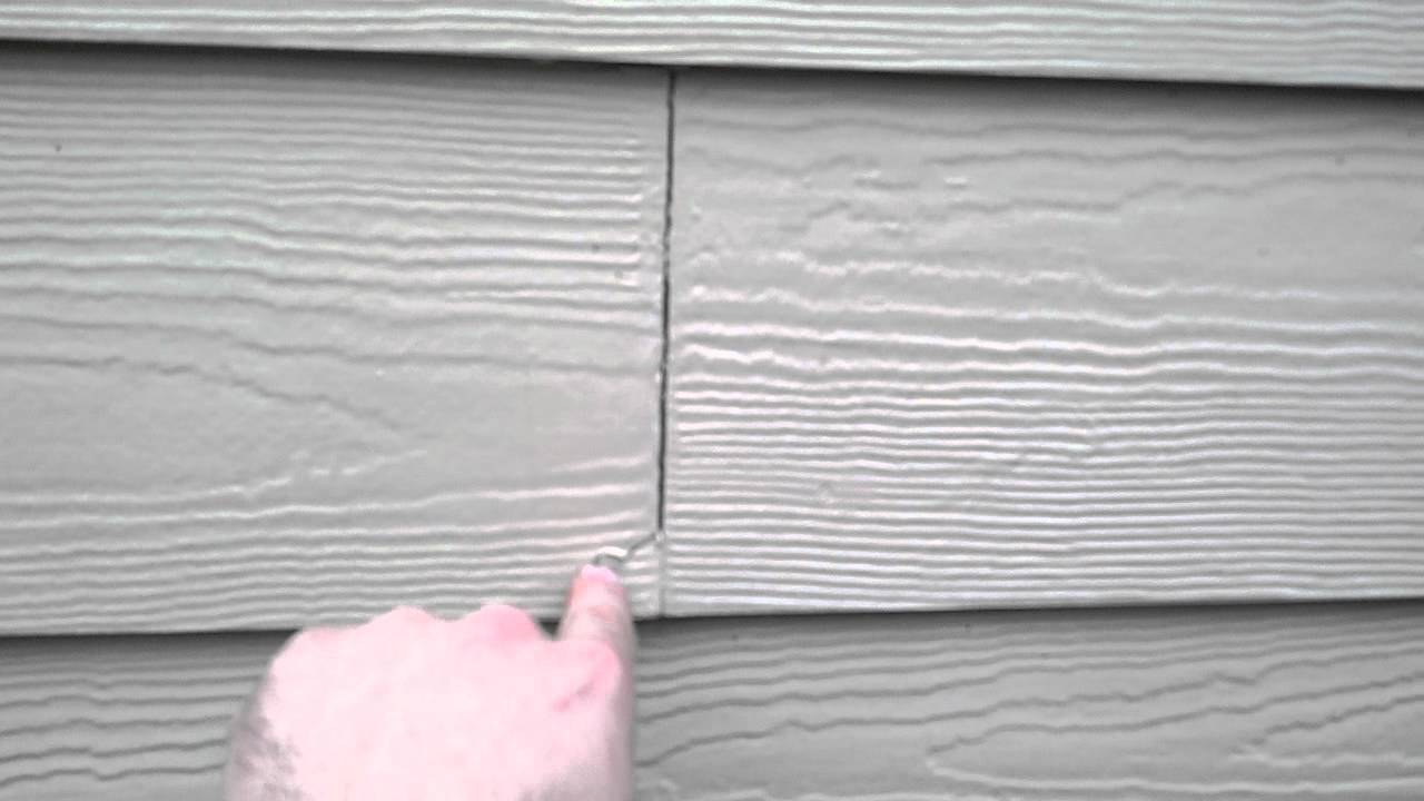
[sps_html tag=”img” src=”https://cdn.northcarolinafinearchitecture.com/2026/05/treatment-of-field-joints-butt-joints-on-hardieplank-lap-siding-primed-pertaining-to-stop-treating-lap-joints-like-butt-joints-and-avoid-catastrophic-failures.jpg” alt=”Treatment Of Field Joints/Butt Joints On Hardieplank Lap Siding (Primed … pertaining to Stop treating lap joints like butt joints and avoid catastrophic failures” style=”width: 100%; height: auto;”]
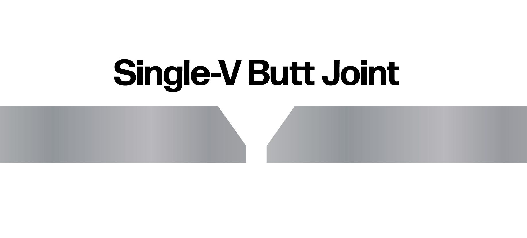
[sps_html tag=”img” src=”https://cdn.northcarolinafinearchitecture.com/2026/05/butt-joint-advantages-and-disadvantages-at-sara-sheridan-blog-pertaining-to-stop-treating-lap-joints-like-butt-joints-and-avoid-catastrophic-failures.jpg” alt=”Butt Joint Advantages And Disadvantages At Sara Sheridan Blog pertaining to Stop treating lap joints like butt joints and avoid catastrophic failures” style=”width: 100%; height: auto;”]