Let’s be honest. When you hear "shear wall design," your brain probably flashes to a dense thicket of equations, cryptic code sections, and that nagging fear of missing a single comma in a boundary element detail. It’s enough to make even the most seasoned structural engineer reach for a strong cup of coffee. But here’s the thing: it doesn’t have to be a nightmare. In fact, once you strip away the academic fluff, designing concrete shear walls per ACI 318 is really just about understanding how forces flow and giving them a clear path to the ground.
We’ve all been there. Staring at a screen late at night, wondering if that special boundary element is actually required or if you’re just being overly conservative. The code has evolved, especially after those tough lessons from earthquakes in Chile and New Zealand years back. By 2026, the tools we use are smarter, but the core principles remain rooted in physics and safety. This isn’t about memorizing every clause in Chapter 11 or 18. It’s about building an intuition for what the wall needs to do, so you can design it with confidence rather than anxiety.
Understanding the Role of Shear Walls in Modern Structures
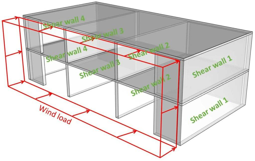
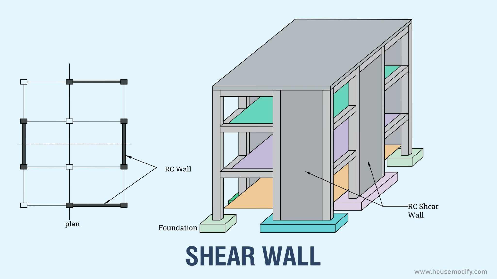
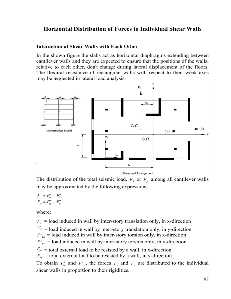
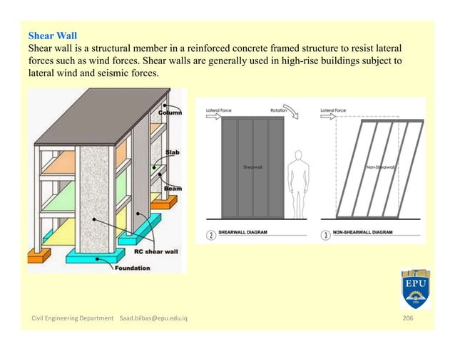
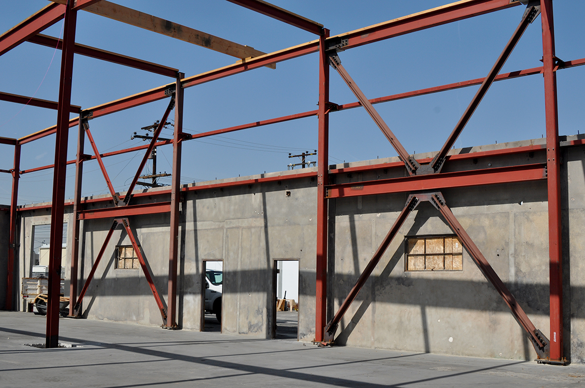
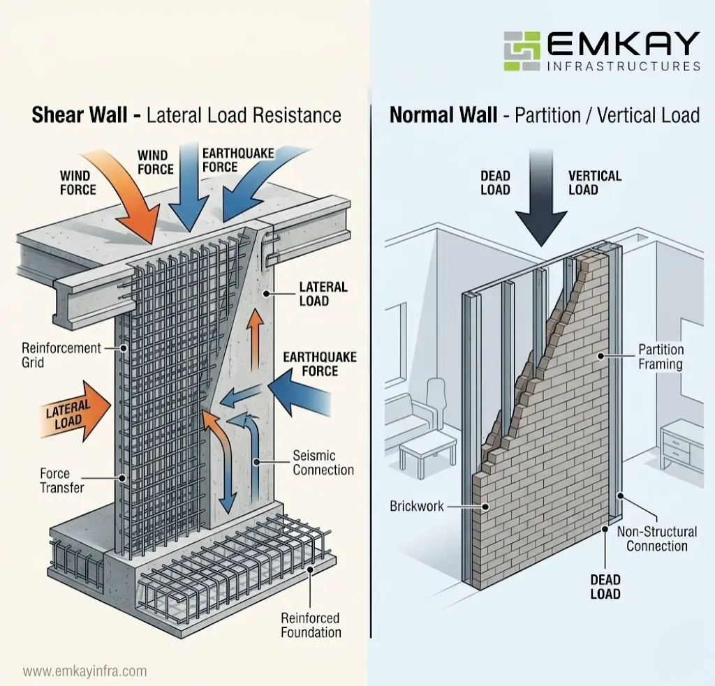
Think of a shear wall as the backbone of a building’s lateral system. While columns and beams handle the gravity loads—the weight of people, furniture, and the structure itself—shear walls take on the horizontal pushes and pulls. These come from wind gusts rattling the windows or seismic waves shaking the foundation. Without them, a building might sway too much, crack, or worse, collapse under lateral stress. They are crucial for enhancing the lateral stability and structural resilience of modern high-rises and mid-rise buildings alike.
But not all walls are created equal. In the world of ACI 318, we distinguish between ordinary and special reinforced concrete shear walls. The difference? Ductility. Special shear walls are designed to bend and deform without breaking during a major earthquake, absorbing energy like a shock absorber. This distinction became crystal clear after the unsatisfactory performance of many walls in the 2010 Chile and 2011 Christchurch earthquakes. Those events triggered significant changes in ACI 318-14, which carried forward into ACI 318-19 and the current 2026 standards. Knowing which category your wall falls into is the first step to avoiding design headaches.
So, how do you decide? It often comes down to the Seismic Design Category (SDC) and the risk level of the structure. If you’re in a high-seismic zone, you’re likely looking at special shear walls. These require stricter detailing, tighter reinforcement spacing, and robust boundary elements. It’s not just about strength; it’s about ensuring the wall can sustain damage without losing its load-carrying capacity. Grasping this fundamental role helps you see the code requirements not as arbitrary rules, but as necessary safeguards for human life.
Navigating the Key Changes in ACI 318-19 and Beyond
If you learned concrete design a decade ago, some of today’s requirements might feel like a foreign language. The shift from ACI 318-11 to ACI 318-14 was a watershed moment, driven by real-world failures. The code writers realized that previous detailing practices weren’t enough to prevent brittle failure in tall, slender walls. Since then, updates in ACI 318-19 and subsequent editions through 2026 have refined these rules, focusing heavily on boundary elements and web reinforcement.
One of the biggest shifts is the emphasis on displacement-based design checks. It’s no longer enough to just check forces; you have to consider how much the wall will drift. This is where things get tricky for many engineers. The code now requires a more rigorous evaluation of whether a wall needs special boundary elements based on strain limits at the extreme fibers. If the concrete crushes before the steel yields, you’ve got a problem. The updated provisions ensure that the confined concrete in boundary zones can handle high compressive strains during seismic events.
Another key update involves the treatment of horizontal and vertical reinforcement. As of recent updates, including features seen in software modules by early 2025, there’s clearer guidance on defining reinforcement for multi-story walls with varying geometries. The code now better addresses walls with openings and irregular shapes, which were previously gray areas. Staying current with these changes isn’t just about compliance; it’s about leveraging improved safety margins. Ignoring them can lead to over-designed, expensive walls or, worse, under-designed ones that fail when it matters most.
The Critical Importance of Boundary Elements
Boundary elements are the unsung heroes of shear wall design. Located at the ends of the wall, these confined zones act like the crumple zones in a car. They absorb the intense compression and tension forces that concentrate at the wall edges during lateral loading. Without proper boundary elements, the concrete at the edges can spall and crush, leading to a sudden, catastrophic loss of strength. This is why ACI 318 places such heavy emphasis on their design and detailing, particularly for special shear walls.
Determining when a boundary element is required used to be a simple check, but now it’s more nuanced. You typically look at the neutral axis depth and the strain in the extreme concrete fiber. If the strain exceeds a certain limit (usually 0.002), you need a special boundary element. This requires a bit of iteration. You assume a reinforcement layout, calculate the strains, and check if your assumption holds. It’s a bit of a chicken-and-egg problem, but modern software like ideCAD or ASDIP CONCRETE automates much of this verification, generating interaction diagrams to help you visualize the capacity.
Detailing these elements is where the rubber meets the road. You need closely spaced hoops or cross-ties to confine the concrete. The spacing isn’t arbitrary; it’s calculated to ensure the core concrete remains intact even when the outer shell cracks. Think of it like wrapping a bundle of sticks tightly so they don’t splay out under pressure. Getting this wrong is a common mistake. Engineers sometimes skimp on the ties or use inadequate anchorage, thinking the vertical bars are enough. They aren’t. The confinement is what provides the ductility. So, pay attention to the hook details and spacing limits. It’s tedious, sure, but it’s what keeps the building standing.
Web Reinforcement and Shear Capacity Checks
While boundary elements handle the bending, the web of the wall—the main body between the boundaries—handles the shear. This is the diagonal cracking force that tries to slice the wall in half. ACI 318 Chapter 11 provides the framework for calculating shear capacity, but it’s easy to get lost in the variables. The basic idea is that the concrete provides some shear resistance, and the horizontal reinforcement picks up the rest. But in seismic designs, we often ignore the concrete contribution to be conservative, relying entirely on the steel.
Choosing the right amount of horizontal and vertical web reinforcement is a balancing act. You need enough steel to control crack widths and provide ductility, but not so much that it becomes impossible to place the concrete. The code specifies minimum reinforcement ratios, usually around 0.0025 for horizontal bars in special walls. But don’t just slap in the minimum and call it a day. Consider the aspect ratio of the wall. Tall, slender walls behave differently than short, squat ones. A wall with a height-to-length ratio greater than 2 acts more like a cantilever beam, while a lower ratio means shear dominates the behavior.
Spacing is another practical headache. Bars need to be close enough to intercept potential cracks. Typically, you’ll see #4 or #5 bars spaced at 12 to 18 inches on center. But remember, these bars need to be anchored properly into the boundary elements. If they just stop short, they can’t do their job. It’s like trying to pull a rope that isn’t tied down. Also, consider constructability. Can the concrete actually flow around all those bars? If the cage is too dense, you’ll get honeycombing, which weakens the wall. Talk to your contractor early. Their feedback on rebar congestion can save you from a logistical nightmare on site.
Practical Steps for Streamlined Design Workflow
Designing shear walls doesn’t have to be a linear, painful slog. A streamlined workflow can save hours and reduce errors. Start with a clear understanding of the loads. Are you dealing with wind or seismic? What’s the drift limit? Get these numbers solid before you open your design software. Next, make a preliminary sizing decision. Use rule-of-thumb thicknesses based on story height and span. For example, a 10-inch wall might work for a mid-rise, but a high-rise might need 18 inches or more. This initial guess gives you a starting point for analysis.
Use technology to your advantage, but don’t trust it blindly. Tools like ENERCALC or CalcBook are great for handling the repetitive calculations, especially for multi-story walls with varying dimensions. As of 2025, many of these modules support direct input for ACI 318-19 and later, allowing you to define horizontal and vertical reinforcement easily. However, always verify the output. Check the interaction diagrams. Do the capacity curves envelop your demand points? If not, adjust your reinforcement or wall thickness. It’s an iterative process, but keeping a spreadsheet handy for quick sanity checks can catch software glitches or input errors.
Documentation is key. Don’t just print the final design. Keep a record of your assumptions, load paths, and key decisions. Why did you choose a special boundary element here? What was the controlling drift case? This narrative helps during peer reviews and plan checks. It also helps you when you revisit the project months later. Clear, concise notes transform a confusing design into a transparent, defensible one. And remember, communication with the architect is vital. Sometimes, moving a wall a few feet or changing an opening size can drastically simplify the structural design. Collaboration beats calculation every time.
Common Pitfalls and How to Avoid Them
Even experienced engineers trip up on shear wall design. One common pitfall is ignoring the interaction between axial load and bending. Shear walls rarely carry just lateral loads; they also support gravity loads from floors above. This axial load can significantly affect the wall’s capacity. A high axial load increases shear strength but reduces ductility. Failing to account for this combination can lead to unsafe designs. Always use P-M (axial-moment) interaction diagrams to check the combined effects. Don’t rely on simplified hand calculations for complex loading scenarios.
Another frequent mistake is poor detailing of lap splices. Rebar isn’t infinite; you have to splice it. In plastic hinge regions—where the wall is expected to yield—lap splices are generally prohibited or strictly regulated. If you must splice, it needs to be done with mechanical couplers or well-confined laps outside the critical zone. Placing a lap splice in the middle of a boundary element where stresses are highest is a recipe for failure. It’s a small detail that’s easy to overlook on a busy drawing set, but it’s critical for performance. Review your shop drawings carefully for this.
Finally, don’t underestimate the importance of construction tolerances. A wall that’s out of plumb or has misplaced rebar won’t perform as designed. Specify clear tolerances in your documents. And consider the sequence of construction. Pouring a tall wall in one lift can lead to segregation of concrete. Lift heights, cold joints, and formwork pressure all matter. Engage with the construction team early to identify potential issues. A design that looks perfect on paper but is unbuildable is a failed design. Anticipating these real-world constraints makes you a better engineer and saves everyone from headaches down the line.
Mastering ACI 318 concrete shear wall design isn’t about memorizing every equation. It’s about understanding the story the wall tells. It’s about knowing how forces travel, where they concentrate, and how to guide them safely to the ground. By focusing on the fundamentals—boundary elements, web reinforcement, and ductility—you can cut through the complexity. The code is there to help, not hinder, if you approach it with the right mindset. Remember the lessons from past earthquakes. They shaped the rules we follow today in 2026, making our buildings safer and more resilient.
Keep your workflow organized. Use tools wisely, verify your results, and communicate clearly with your team. Avoid the common traps of ignoring axial-bending interaction or sloppy detailing. And don’t be afraid to ask questions or seek second opinions. Structural engineering is a collaborative effort. When you design with empathy for the builder and respect for the physics, the "headache" fades away. What’s left is the satisfaction of creating something strong, safe, and enduring. So take a deep breath, grab that coffee, and tackle that next shear wall with confidence. You’ve got this.
[sps_html tag=”img” src=”https://cdn.northcarolinafinearchitecture.com/2026/05/shear-wall-force-distribution-structural-analysis-in-how-to-stop-building-twist-the-critical-role-of-balanced-shear-wall-layouts.png” alt=”Shear Wall Force Distribution: Structural Analysis in How to Stop Building Twist The Critical Role of Balanced Shear Wall Layouts” style=”width: 100%; height: auto;”]
[sps_html tag=”img” src=”https://cdn.northcarolinafinearchitecture.com/2026/05/what-is-shear-wall-and-its-types-at-sarah-alanson-blog-intended-for-how-to-stop-building-twist-the-critical-role-of-balanced-shear-wall-layouts.jpg” alt=”What Is Shear Wall And Its Types At Sarah Alanson Blog intended for How to Stop Building Twist The Critical Role of Balanced Shear Wall Layouts” style=”width: 100%; height: auto;”]
[sps_html tag=”img” src=”https://cdn.northcarolinafinearchitecture.com/2026/05/shear-wall-pdf-civil-engineering-industry-industries-in-how-to-stop-building-twist-the-critical-role-of-balanced-shear-wall-layouts.jpg” alt=”Shear Wall | Pdf | Civil Engineering Industry | Industries in How to Stop Building Twist The Critical Role of Balanced Shear Wall Layouts” style=”width: 100%; height: auto;”]
[sps_html tag=”img” src=”https://cdn.northcarolinafinearchitecture.com/2026/05/shear-wall-vs-normal-wall-key-structural-differences-with-regard-to-shear-wall-design.webp” alt=”Shear Wall Vs Normal Wall: Key Structural Differences with regard to Shear Wall Design” style=”width: 100%; height: auto;”]
[sps_html tag=”img” src=”https://cdn.northcarolinafinearchitecture.com/2026/05/shear-wall-design-step-by-step-guide-structural-basics-for-shear-wall-design.jpg” alt=”Shear Wall Design {Step-By-Step Guide} - Structural Basics for Shear Wall Design” style=”width: 100%; height: auto;”]