The alignment bench smells faintly of acetone and black anodized aluminum. Under the low-intensity green task light, a cleanroom wiper snags momentarily on a microscopic speck of dust near the edge of an 8-inch parabolic primary mirror. That speck, invisible to the casual observer, is enough to scatter fractional percentages of an incoming wavefront, degrading an otherwise pristine Airy disk. Designing reflective optical systems is an exercise in managing physics at its most unforgiving. Every millimeter of aperture, every micron of focal length drift, alters the thermal, mechanical, and mathematical reality of how photons travel from distant celestial sources or industrial laser cavities to a tight, high-intensity focal plane.
For decades, optical designers have wrestled with the physical compromises inherent in folding light. Whether you are laying out a Newtonian tube for deep-sky imaging, designing a Ritchey-Chrétien astrograph for an automated observatory network, or routing high-power laser beams through reflective relay optics, the interplay between your aperture diameter ($D$) and your focal length ($f$) dictates everything. It sets your light-gathering capacity, establishes your diffraction-limited resolution, and determines the physical scale of your final image. Getting these parameters right requires more than plugging numbers into standard equations; it demands an intimate understanding of geometrical optics, mechanical tolerances, and the relentless pull of thermal expansion.
The modern optical landscape requires unprecedented precision. As automated surveys expand and industrial laser processing systems push higher power densities, optical layouts cannot afford the luxury of trial-and-error prototyping on the main shop floor. Every component, from the primary mirror’s clear aperture to the precise placement of the secondary baffle, must be modeled with absolute rigor. Understanding how light interacts with boundary conditions, how central obstructions alter modulation transfer functions (MTF), and how to balance focal ratios transforms an unpredictable prototype into a reliable, diffraction-limited instrument.
The Geometry of Light Collection and Wavefront Propagation
When light enters an optical reflector layout, it is fundamentally a collection of electromagnetic wavefronts carrying spatial and spectral information. The primary mirror acts as the ultimate collector, intercepting a cylindrical column of light whose diameter is defined by the entrance aperture. The physical diameter of this aperture ($D$) is the single most critical determinant of two competing optical characteristics: light-gathering power and angular resolution. Light-gathering power scales exponentially with the square of the aperture diameter, meaning that doubling your mirror diameter quadruples the number of photons hitting your focal plane within a given exposure window.
Resolution, however, is governed by wave optics rather than simple geometry. According to the Rayleigh criterion, the minimum resolvable angular separation between two point sources is inversely proportional to the aperture diameter. A larger aperture compresses the central diffraction maximum of the Airy disk, allowing finer spatial features to be resolved. Yet, collecting these photons is only half the battle. Once the wavefront strikes the reflective surface, its trajectory is fundamentally altered. Concave parabolic or spherical geometries redirect the parallel incoming rays toward a common convergence point known as the focal point.
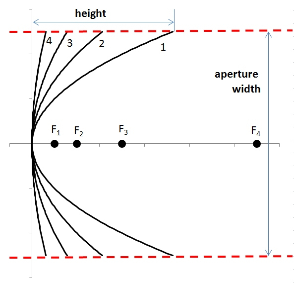
The distance from the reflective surface to this convergence point defines the focal length ($f$). When you combine these two core parameters, you arrive at the focal ratio, commonly expressed as the f-number ($f/D$). This dimensionless metric governs the plate scale and the physical concentration of energy at the focal plane. A "fast" optical system with a low f-number (such as $f/3$ or $f/4$) concentrates photons into a compact area, delivering high image brightness per unit area but demanding extreme alignment tolerances. Conversely, a "slow" system ($f/10$ or higher) spreads the light over a larger physical area, reducing image brightness but easing the mechanical tolerances required to maintain sharp focus across a wide field of view.
Balancing Aberrations, Obstructions, and the Modulation Transfer Function
Every optical reflector layout involves compromises. The introduction of a secondary mirror in folded designs like Cassegrain, Gregorian, or Dall-Kirkham configurations introduces a central obstruction. While essential for routing the light path back through a perforation in the primary mirror or out to a side-mounted eyepiece, this obstruction alters the diffraction pattern of the system. Instead of clean, concentric rings surrounding a bright central maximum, a central obstruction redistributes energy from the central peak into the surrounding diffraction rings. This reduces the contrast of medium-frequency spatial details, a phenomenon clearly visible in the system’s Modulation Transfer Function (MTF).
Spherical aberration, coma, and astigmatism lurk around every corner of optical layout design. Uncorrected spherical aberration prevents marginal rays from meeting at the exact same focal point as paraxial rays, resulting in a blurred focal spot regardless of how meticulously you adjust the focuser. Parabolic primary mirrors naturally correct for on-axis spherical aberration, but they introduce off-axis coma, flaring off-axis star images into comet-like shapes. To counteract this, advanced reflector designs utilize hyperbolic secondary surfaces or specialized corrector lenses placed near the focal plane, balancing wave errors across a flat field.
Thermal gradients within the optical tube assembly introduce localized refractive index variations in the surrounding air and alter the figure of the glass substrates. Low-expansion glass ceramics like Zerodur or Pyrex mitigate substrate distortion, but the mechanical cell holding the mirror must be engineered with floating lateral supports and precise point-support arrays (such as 9-point or 18-point flotation cells for larger apertures). If an aperture stop or mirror cell pinches the glass by even a few microns, astigmatism immediately manifests at the focal point, ruining the optical wavefront before it ever reaches the sensor or eyepiece.
Methodical Workflow for Designing and Optimizing Reflector Layouts
Laying out a high-performance optical reflector requires a systematic engineering workflow. Skipping a step in the initial ray-tracing phase invariably leads to costly mechanical redesigns during fabrication.
- Step 1 (Determine System Requirements and Constraints): Define your target operational wavelength, required field of view, physical envelope constraints, and intended use case—whether wide-field celestial imaging or high-power laser beam delivery—before selecting an optical architecture.
- Step 2 (Establish Aperture and Focal Length Parameters): Calculate the minimum required aperture diameter ($D$) based on resolution and light-throughput targets, then select the focal length ($f$) to achieve your desired image scale and f-number.
- Step 3 (Select the Optical Configuration and Ray Trace): Input your parameters into optical design software (such as Zemax OpticStudio or Code V) to model Newtonian, Cassegrain, or three-mirror anastigmat configurations, mapping paraxial and marginal ray paths.
- Step 4 (Optimize Surface Figures and Baffling): Adjust conic constants, secondary mirror spacings, and clear apertures while monitoring wavefront error (RMS and peak-to-valley), Strehl ratio, and stray-light suppression using internal knife-edge baffles.
- Step 5 (Tolerancing and Mechanical Integration): Run Monte Carlo tolerance analyses to evaluate how tilt, decentering, and axial desspace affect system performance, ensuring the mechanical housing can maintain alignment under real-world gravity and thermal loads.
Navigating Common Pitfalls and Field-Tested Workarounds
Optical design theory looks pristine on a computer monitor, but physical fabrication and assembly introduce stubborn real-world complications. Recognizing these pitfalls early saves months of debugging.
- Pitfall 1 (Undersizing the Secondary Mirror and Baffles): Designers often calculate secondary mirror size based strictly on axial marginal rays, ignoring field illumination falloff. Workaround: Always model full-field vignetting and ensure the minor axis of the secondary mirror is oversized by 5% to 10% to fully illuminate off-axis field points without cutting off the beam footprint.
- Pitfall 2 (Ignoring Thermal Equilibrium Times): Large monolithic glass substrates act as thermal batteries, shedding heat slowly and creating internal air turbulence that destroys seeing conditions. Workaround: Integrate active boundary-layer cooling fans and specify low-expansion substrates to reach thermal equilibrium rapidly upon deployment.
- Pitfall 3 (Overlooking Central Obstruction MTF Degradation): Designing a system with an excessively large central obstruction (>35% of the aperture diameter) to achieve a short tube length severely damages high-frequency contrast. Workaround: Keep central obstructions below 30% for high-resolution imaging, balancing tube physical length against acceptable contrast loss.
- Pitfall 4 (Inadequate Structural Stiffness in the Optical Tube): Flexure in truss tubes or solid aluminum OTAs causes focal point drift as the telescope or instrument tracks across the sky or rotates in a gantry. Workaround: Use finite element analysis (FEA) to model structural deflection and employ carbon fiber composite trusses with zero-coefficient-of-thermal-expansion nodes.
- Pitfall 5 (Neglecting Stray Light and Internal Reflections): Unbaffled tube interiors and reflective internal walls scatter stray light directly onto the focal plane, washing out faint contrast details. Workaround: Apply ultra-flat, high-absorption flocking material or carbon-nanotube black coatings to all interior surfaces and position knife-edge stray-light baffles at calculated conjugate planes.
Holistic Perspectives and Long-Term Impact on High-Precision Instruments
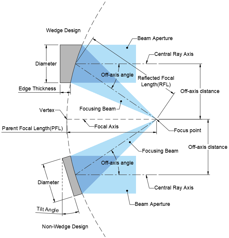
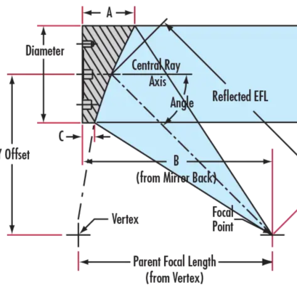
The evolution of optical reflector layouts extends far beyond traditional telescopes. Modern manufacturing techniques, including deterministic computer-controlled optical surfacing, magnetorheological finishing (MRF), and freeform diamond turning, have unlocked asymmetrical and off-axis optical designs that were once mathematically impossible to fabricate reliably. Off-axis parabolic (OAP) mirrors and three-mirror anastigmats eliminate central obstructions entirely, offering unobstructed apertures with pristine MTF performance across broad spectral bands from the deep ultraviolet to the far infrared.
From an economic and operational standpoint, the push toward optimized aperture layouts reduces payload mass for space-based observatories and lowers structural overhead for ground-based facilities. In industrial sectors, precise laser beam delivery systems rely on scaled-down reflective layouts to manage thermal blooming and high-power damage thresholds. As materials science introduces novel ceramic composites and additive manufacturing processes for lightweight, topologically optimized mirror cells, the boundary between structural support and optical performance continues to dissolve.
Sustainable optical engineering also demands longevity and field-serviceability. Optical coatings—whether enhanced aluminum, protected silver, or multi-layer dielectric stacks—degrade over time due to oxidation, humidity, and particulate bombardment. Designing reflector layouts with easily swappable primary and secondary mirror cells ensures that instruments can be recoated and recalibrated without requiring complete structural teardowns, extending operational lifecycles by decades.
Actionable Recommendations and Key Takeaways
Mastering focal points and aperture diameters in reflector layouts requires balancing mathematical precision with hands-on mechanical discipline. To consistently deliver diffraction-limited performance in your optical projects, implement the following structured framework:
- Prioritize Wavefront Error Metrics: Never rely solely on geometric spot diagrams; always optimize your design for RMS wavefront error and target a Strehl ratio of 0.80 or higher (the Maréchal criterion) to guarantee diffraction-limited performance.
- Maintain Rigorous Tolerancing Protocols: Execute Monte Carlo tolerance runs simulating worst-case tilt and decenter scenarios to ensure your optomechanical housing can be realistically manufactured and aligned in the field.
- Control the Thermal Environment: Isolate heat sources, specify low-expansion mirror substrates, and incorporate active thermal management to eliminate internal air currents that distort the incoming wavefront.
- Optimize Baffling and Field Illumination: Balance central obstruction size against field illumination uniformity, utilizing internal knife-edge baffles to suppress stray light and maximize contrast at the focal plane.
The pursuit of optical perfection is an iterative journey through physics, engineering, and craftsmanship. When you finally lock down a reflector layout—balancing aperture diameter against focal length, taming aberrations with precise conic surfaces, and housing the assembly in a rigid, thermally stable chassis—the result is more than just hardware. It is an instrument of clarity, capable of gathering ancient photons from the edge of the visible universe or directing high-energy beams with atomic precision.
As you step away from the optical bench and review your ray-trace models, remember that theory and practice must constantly inform one another. The numbers on the screen are only as good as the mechanical constraints holding the glass in place. Keep your tolerances tight, respect the thermal behavior of your materials, and never underestimate the impact of a clean optical surface. The universe reveals its details only to those willing to respect the subtle laws governing the path of light.