Low-voltage outdoor lighting transforms residential architecture and garden landscapes after dark, elevating curb appeal, illuminating walkways, and highlighting custom exterior masonry. However, many ambitious DIY outdoor lighting projects encounter a frustrating flaw upon first activation: fixtures positioned closest to the power source shine brilliantly, while pathway lights and accent uplights at the far end of the run appear dim, yellowish, or flicker erratically. This issue is not caused by defective light fixtures, but by electrical voltage drop along the cable line. Because residential landscape systems operate on low-voltage 12-volt alternating current (AC), conductor resistance over long wire lengths causes voltage to decay much faster than in standard 120-volt household branch circuits. Designing a reliable, professional-grade landscape lighting system requires proper engineering calculations: sizing your transformer with a 20% safety margin, selecting the correct American Wire Gauge (AWG) direct-burial cable, applying voltage drop equations, and using strategic wire layouts to keep every fixture within its optimal operating window.
Core Principles: Understanding Voltage Drop in 12-Volt Outdoor Lighting Runs
All electrical conductors possess internal resistance. According to Ohm’s Law, voltage drop is the product of electrical current (in amperes) and conductor resistance (in ohms), represented as:
Voltage Drop (Vdrop) = Current (I) × Resistance (R)
In standard 120-volt household wiring, a 2-volt drop represents a negligible 1.6% loss, which has virtually no perceptible effect on household appliances. In a 12-volt landscape lighting circuit, however, that identical 2-volt drop represents a massive 16.7% loss of available electrical potential. While vintage halogen landscape bulbs would noticeably yellow and dim below 10.5 volts, modern LED luminaires contain internal driver circuits that require a steady operating threshold—typically between 10.8 volts and 12.0 volts. If line voltage falls below this threshold, LED drivers overheat, flicker, or shut down entirely.
To ensure consistent illumination and long driver lifespans, the engineering goal is to maintain the voltage at the furthest fixture between 10.8 volts and 11.5 volts when powered from a standard 12-volt transformer tap.
Step 1: Calculate Total System Wattage and Select Transformer Capacity with the 80% Rule
Before selecting your underground wire, determine the total electrical load demanding power from your central transformer. Inventory every fixture planned for the outdoor lighting zone and record its individual power rating:
- Sum the wattage: Add together the rated wattage of all luminaires on the circuit. For example, a walkway run featuring ten 3-watt pathway LED fixtures and four 7-watt architectural uplights creates a total baseline load of 58 watts (10 × 3W = 30W; 4 × 7W = 28W; 30W + 28W = 58W).
- Account for Volt-Amps (VA): For LED luminaires with magnetic low-voltage transformers, power factor variations mean actual power draw is measured in Volt-Amps (VA). If fixture specifications list VA ratings, always calculate using VA rather than nominal watts.
- The 80% continuous load safety rule: Electrical codes and professional lighting design standards dictate that a low-voltage transformer should never operate beyond 80% of its rated capacity. Operating a transformer at 100% capacity accelerates internal coil wear and triggers premature thermal breaker trips during warm summer nights.
To size your transformer correctly, divide your total fixture load by 0.80 (or multiply by 1.25):
Minimum Transformer Capacity = 58 Watts / 0.80 = 72.5 Watts
Because transformers are manufactured in standard capacities (such as 75W, 150W, 300W, and 600W), select the next standard size above your calculation. For our 58-watt system, a 75-watt or 150-watt stainless steel multi-tap transformer provides the ideal balance between capacity and future fixture expansion. When configuring timers and photocells on your transformer, consult our troubleshooting guide on what to do when outdoor lights turn on at the wrong time to ensure internal clocks and daylight sensors match seasonal shifts.
Step 2: Understand American Wire Gauge (AWG) Cable Resistance for Direct Burial Wire
Outdoor low-voltage landscape lighting uses specialized twin-conductor direct-burial cable (UF-rated copper). In the American Wire Gauge (AWG) sizing system, smaller gauge numbers denote thicker copper conductors with lower electrical resistance.
In electrical design standards, such as the Texas Department of Transportation Highway Illumination Manual, conductor resistance is recognized as a direct function of wire gauge and total distance, requiring loop calculations that account for both the outbound and return conductors. Standard direct-burial pure copper landscape wire exhibits the following round-trip loop resistance values at typical operating temperatures:
- 16 AWG: Approximately 4.02 ohms per 1,000 feet of loop length (suitable only for very short runs under 30 feet with minimal wattage).
- 14 AWG: Approximately 2.52 ohms per 1,000 feet of loop length (ideal for short branch runs up to 50 feet with moderate LED loads).
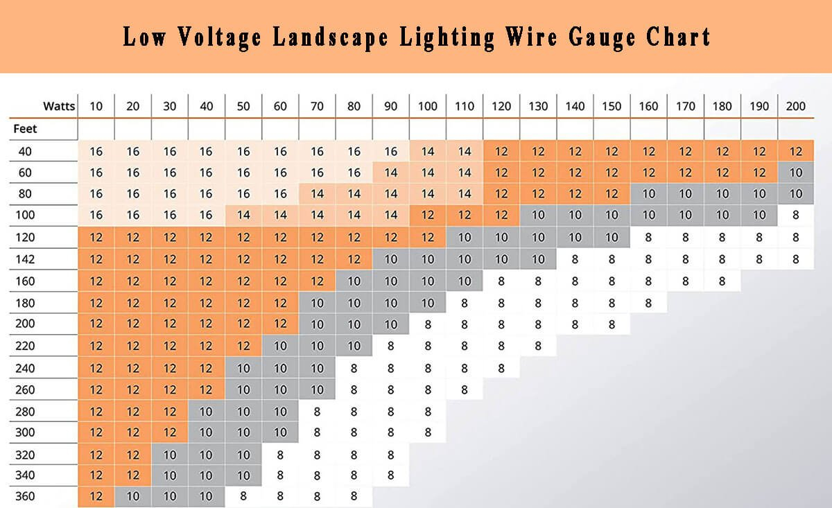
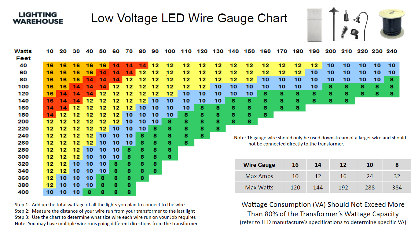
- 12 AWG: Approximately 1.59 ohms per 1,000 feet of loop length (the universal workhorse standard for residential landscape runs up to 100–120 feet).
- 10 AWG: Approximately 0.99 ohms per 1,000 feet of loop length (heavy-gauge conductor required for long runs exceeding 120 feet or heavy commercial-grade loads).
Never skimp on cable thickness. Running undersized 16-gauge wire over long distances guarantees excessive voltage drop and forces you to replace buried underground wiring later.
Step 3: Apply the Low-Voltage Drop Formula to Determine Conductor Gauge
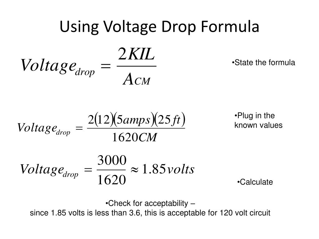
To verify whether a planned wire run will deliver sufficient voltage to the final fixture, apply the landscape lighting voltage drop formula. Because current flows through two conductors (out to the light and back to the transformer), total circuit length is twice the one-way trench distance:
Vdrop = (2 × Length × Total Watts × Wire Resistance Constant) / 1,000
Where:
- Length: One-way distance from the transformer to the furthest fixture (in feet).
- Total Watts: Cumulative wattage of all fixtures connected along this specific cable run.
- Wire Resistance Constant: 1.59 for 12 AWG copper, 2.52 for 14 AWG copper, and 0.99 for 10 AWG copper.
Let’s calculate an illustrative example: assume a homeowner runs 100 feet of 12 AWG copper cable to power 60 watts of LED pathway fixtures from a 12-volt transformer tap:
Vdrop = (2 × 100 × 60 × 1.59) / 1,000 = 19,080 / 1,000 = 1.91 Volts
Subtracting this loss from the 12.0-volt power source yields a terminal voltage of:
Terminal Voltage = 12.0V – 1.91V = 10.09 Volts
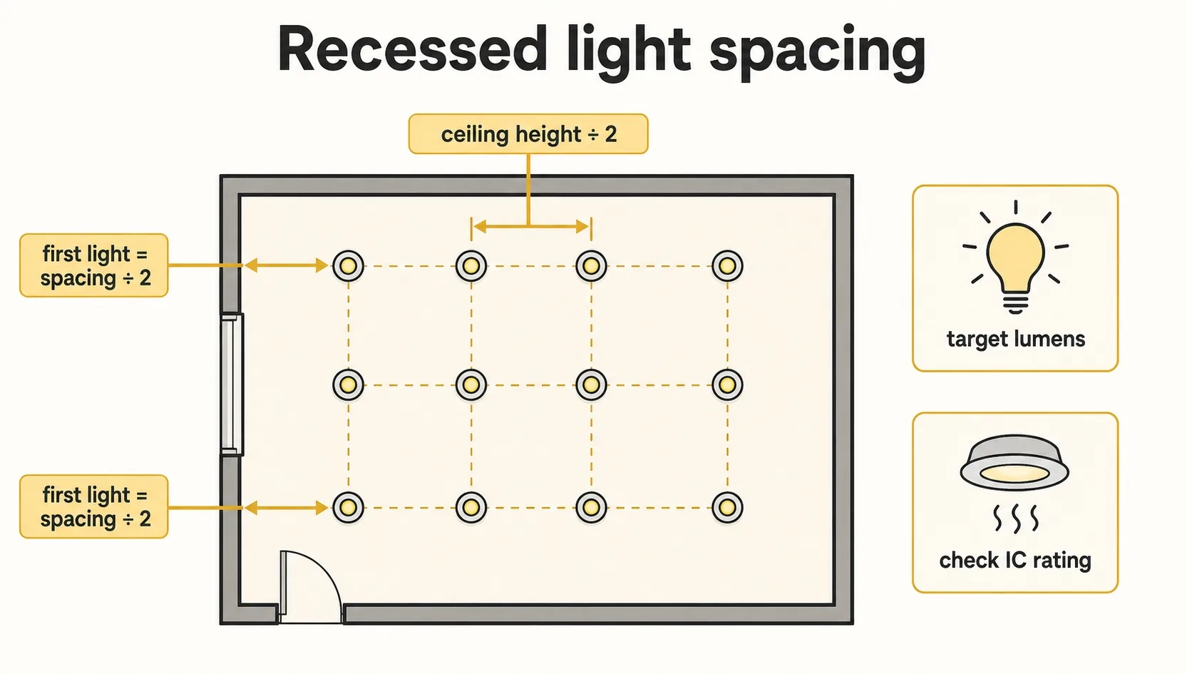
At 10.09 volts, the end fixtures sit below the safe 10.8-volt operating threshold. As highlighted by engineering reference tools such as LumenCalculator, maintaining total line voltage loss under 1.2 volts ensures fixtures operate safely within their peak efficiency window. Similar to calculating indoor lumens and beam spreads in our guide on how to calculate recessed lighting spacing, outdoor architectural illumination relies on rigorous mathematical planning rather than arbitrary layout guesswork. To fix this voltage deficit, you can either step up to 10 AWG wire or employ strategic layout methods.
Step 4: Strategic Cable Layouts to Balance Line Voltage Across Distant Fixtures
Rather than relying solely on thicker, more expensive wire, experienced landscape lighting designers use advanced circuit layout topologies to dramatically reduce voltage drop:
- The Straight Daisy-Chain (Avoid for Long Runs): Running cable from the transformer directly to fixture 1, then fixture 2, onward to fixture 10 creates the worst voltage drop imbalance. The first fixture receives 12.0 volts, while the last fixture receives the cumulative drop of the entire line.
- The Center-Feed (T-Method): Run a heavy 10 AWG or 12 AWG feed cable from the transformer straight to the geographic center of your lighting run without connecting any fixtures along the way. At the center point, splice into two separate branch lines extending outward in opposite directions. This cuts effective run length and current in half on each branch, slashing voltage drop by up to 75% without adding extra wire gauge.
- The Hub or Star Topology: In clustered planting beds or patio groupings, run an uninterrupted home-run cable from the transformer to a central weatherproof junction hub. Connect each nearby fixture to the hub using equal lengths of 14 AWG cable. Because every fixture cable is identical in length, each luminaire receives identical voltage.
- The Closed Loop Method: For perimeter walkway lighting that circles back toward the power source, connect the end of the cable run back to the transformer terminals. A closed loop equalizes voltage across all connected luminaires, ensuring consistent lumen output and color temperature.
Step 5: Utilizing Multi-Tap Transformers (13V to 15V) to Compensate for Unavoidable Run Lengths
When landscape layouts require long continuous runs exceeding 120 to 150 feet—such as illuminating an extensive private driveway or distant property boundary—voltage drop becomes unavoidable even with 10 AWG copper cable.
In these challenging scenarios, professional multi-tap transformers provide secondary voltage taps at 13V, 14V, and 15V alongside the standard 12V terminal. These elevated taps compensate precisely for calculated line resistance:
- Calculating tap voltage: If your cable run incurs a calculated 2.0-volt drop over a 150-foot distance, connecting that run to a 14-volt tap delivers approximately 12.0 volts to the end fixtures (14.0V – 2.0V = 12.0V).
- Guarding against over-voltage on initial fixtures: When using high-voltage taps, always measure the voltage at the first fixture on the line using a digital true-RMS multimeter. Never expose modern LED luminaires to voltages exceeding their maximum manufacturer rating (typically 15.0V AC). If the first fixture sits too close to a high-voltage tap, run a dedicated un-tapped home run cable out to the distant zone rather than overdriving nearby lights.
By pairing rigorous wattage calculations and conductor sizing with center-feed topologies and multi-tap adjustments, your outdoor landscape lighting system will deliver crisp, balanced, and energy-efficient illumination for years to come.