You’re standing on the shop floor, torch in hand, looking at a simple L-shaped piece of steel. It’s a clip angle. It looks harmless enough. But that little piece of metal is doing some heavy lifting—literally. It’s holding up a beam, transferring loads, and keeping the structure from swaying like a tree in a hurricane. And right there, on that "outstanding leg," is where things can go sideways if you aren’t careful.
We’ve all seen it. A welder, maybe rushing to meet a deadline, decides to run a bead all the way around the angle. Three sides. Top, bottom, and back. It looks strong. It looks complete. But in the world of structural steel, "looking strong" isn’t the same as being strong. In fact, that extra weld might be introducing hidden stresses, cracking risks, and failure points that nobody sees until it’s too late.
This isn’t just theory. It’s physics. And in 2026, with structures getting taller and loads getting heavier, understanding the nuance of these connections is more important than ever. Let’s break down why we weld the way we do, what happens when we cut corners (or add too many), and how to keep those connections safe without overcomplicating the job.
What Exactly Is an Outstanding Leg?
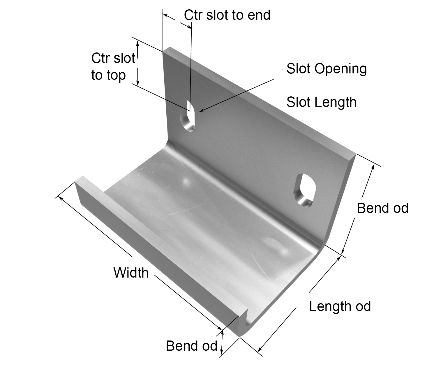
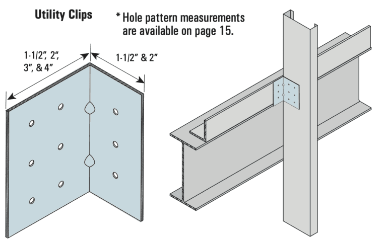
First, let’s get our terms straight. If you’re new to steel detailing, the jargon can feel like a foreign language. A clip angle is basically an L-bracket. One leg gets attached to the supporting column or girder. The other leg sticks out. That sticking-out part? That’s the "outstanding leg."
It’s called "outstanding" not because it’s excellent, but because it stands out from the main support. This leg is usually where the beam sits, or where bolts go through to connect the beam web. When we talk about welding this leg, we’re usually talking about attaching the angle to the column flange or the girder web.
Here’s the thing: the geometry matters. A lot. The American Welding Society (AWS) and AISC (American Institute of Steel Construction) have specific rules about how long those welds should be and where they stop. For instance, welds on the outstanding legs are typically returned at the top for a short distance—about two times the weld size (2t)—and then stopped. They don’t go all the way down. Why? Because steel behaves in weird ways under load, and fighting that behavior with extra weld metal often makes things worse, not better.
The Trap of Over-Welding
It feels counterintuitive, doesn’t it? If one weld is good, three must be better. That’s the instinct. You want to secure that angle so it never moves. So, you weld the vertical side, the top horizontal side, and the bottom horizontal side. You’ve boxed it in.
But here’s the hidden risk: restraint. When you weld all three sides, you create a rigid box. Steel expands when it heats up and contracts when it cools down. During the welding process, that heat input causes distortion. By locking all three sides, you’re trapping those stresses inside the connection. Instead of allowing the angle to flex slightly and distribute the load naturally, you’re creating high-stress concentration points at the corners.
In 2026, we see more high-strength steels being used. These materials are tougher, but they can be more sensitive to rapid cooling and residual stress. Over-welding an outstanding leg can lead to premature cracking, especially in the heat-affected zone (HAZ). It’s like tying a rope so tight it snaps under its own tension. The connection might hold during static testing, but under dynamic loads—like wind or seismic activity—that rigid weld pattern becomes a weak link.
Shear Lag and the Uneven Load Path
Let’s talk about shear lag. It sounds technical, but it’s actually a simple concept. Imagine you’re pulling a wagon by only one handle. The side you’re pulling on takes most of the force, while the other side lags behind. That’s shear lag.
When you weld only one side of the outstanding leg (typically the vertical leg attached to the column), the load transfer isn’t uniform across the entire angle cross-section. The attached leg takes the brunt of the shear force. The outstanding leg, which might be bolted to the beam, has to transfer that load through the angle’s corner.
If you weld the outstanding leg incorrectly—for example, by adding unnecessary welds that stiffen it too much—you disrupt this natural load path. Research from recent studies shows that existing shear design equations accurately predict strength when the connection behaves as intended. But when you introduce unpredictable stiffness through over-welding, those equations no longer apply cleanly. The "lag" becomes uneven, leading to localized yielding or tearing at the toe of the angle.
This is why codes like AISC specify limits. They want the connection to behave predictably. They want the shear to flow smoothly from the beam, through the bolts, into the angle, and down the weld to the column. Disrupting that flow with excessive weld metal on the outstanding leg creates turbulence in the force path. And turbulence in steel structures is bad news.
The Critical Role of the 2t Return
So, if we shouldn’t weld all three sides, what do we do? We use a "return." You’ll often see specs calling for a 2t return at the top of the outstanding leg. "2t" means two times the weld size. If your weld is 1/4 inch, you wrap the weld around the top corner for 1/2 inch.
Why bother? It’s not just for show. That small return serves a crucial purpose: it prevents crack initiation at the start and end of the weld. Welds are weakest at their起止 points (start and stop). By wrapping the weld around the corner, you move the start/stop point away from the highly stressed edge of the angle. It also helps resist "reverse loading"—forces that might try to peel the angle away from the column.
But notice what it doesn’t do. It doesn’t weld the entire top edge. It stops short. AWS guidelines say the weld should stop no more than 4 times the weld size from the outer toe, and not greater than half the leg width. This precision matters. It ensures the weld is long enough to develop the required strength but short enough to avoid the distortions we talked about earlier.
Think of it like stitching a button. You don’t sew around the entire perimeter of the buttonhole; you make a few strong, strategic stitches. Too many stitches bunch up the fabric. Too few, and the button falls off. The 2t return is that sweet spot.
Practical Tips for Welders and Detailers
Knowing the theory is one thing. Doing it right in the field is another. Here are some practical tips to keep in mind whether you’re holding the torch or drawing the plans.
- Check the Print: Always verify the weld symbols. If it shows a fillet weld on one side with a return, don’t add extra welds "just in case." Stick to the spec.
- Control Heat Input: Use the right amperage and travel speed. Overheating the thin leg of the angle can cause warping, which makes bolting the beam difficult later.
- Mind the Gap: Ensure the fit-up between the angle and the column is tight. Large gaps require more weld metal to fill, which increases heat input and distortion.
- Inspect the Toes: Cracks often start at the toe of the weld (where the weld meets the base metal). Make sure the transition is smooth. No undercutting.
- Communicate: If a detail looks wrong or impossible to weld, talk to the engineer. Don’t guess. In 2026, digital models make it easier to clash-check, but human eyes on the shop floor still catch things software misses.
Remember, consistency is key. A messy weld isn’t just ugly; it’s a sign of inconsistent heat and potential weakness. Take your time. Do it right the first time.
Real-World Consequences of Getting It Wrong
What happens if we ignore these rules? It’s not always a dramatic collapse. Often, it’s subtle. You might see cracking in the weld after a few years of service. Or, during a high-wind event, the connection might deform more than expected, causing damage to non-structural elements like drywall or glass.
In extreme cases, though, the consequences are severe. There have been instances where improper welding of clip angles contributed to connection failures during seismic events. The rigidity introduced by over-welding caused brittle fracture rather than ductile yielding. The steel didn’t bend; it snapped.
Consider a recent retrofit project in California. Engineers found that decades-old connections had been over-welded by well-meaning but misinformed workers. The extra welds had created stress concentrations that led to micro-cracking. The fix? Careful grinding and reinforcement, costing ten times more than if it had been done correctly initially.
It’s a reminder that steel construction is a chain. Every link matters. The clip angle might seem like a small link, but if it fails, the whole chain breaks. And in our industry, we don’t get second chances.
Welding outstanding legs on clip angles isn’t rocket science, but it is precision work. It requires understanding not just how to lay a bead, but why we lay it that way. The hidden risks—distortion, shear lag, stress concentration—are real, but they’re manageable if we respect the physics.
Stick to the codes. Use the 2t return. Avoid the temptation to over-weld. Keep the load path clear and predictable. And always, always remember that the goal isn’t just to join two pieces of metal. It’s to create a connection that will stand the test of time, weather, and load.
Next time you’re in the shop, take a second to look at that clip angle. See it not just as a piece of steel, but as a critical component in a larger system. Treat it with care, and it’ll do its job perfectly. After all, that’s what we’re all here for: building things that last.
[sps_html tag=”img” src=”https://cdn.northcarolinafinearchitecture.com/2026/05/clip-angle-definition-construction-at-melinda-hawthorne-blog-pertaining-to-from-33-to-97-mils-how-thickness-impacts-your-clip-angle-strategy.jpg” alt=”Clip Angle Definition Construction At Melinda Hawthorne Blog pertaining to From 33 to 97 Mils How Thickness Impacts Your Clip Angle Strategy” style=”width: 100%; height: auto;”]
[sps_html tag=”img” src=”https://cdn.northcarolinafinearchitecture.com/2026/05/what-does-mil-stand-for-in-thickness-inkable-label-co-regarding-from-33-to-97-mils-how-thickness-impacts-your-clip-angle-strategy.png” alt=”What Does Mil Stand For In Thickness? - Inkable Label Co. regarding From 33 to 97 Mils How Thickness Impacts Your Clip Angle Strategy” style=”width: 100%; height: auto;”]
[sps_html tag=”img” src=”https://cdn.northcarolinafinearchitecture.com/2026/05/aisi-publishes-cold-formed-steel-clip-angle-design-guide-2021-ed-intended-for-from-33-to-97-mils-how-thickness-impacts-your-clip-angle-strategy.jpeg” alt=”Aisi Publishes Cold-Formed Steel Clip Angle Design Guide, 2021 Ed … intended for From 33 to 97 Mils How Thickness Impacts Your Clip Angle Strategy” style=”width: 100%; height: auto;”]
[sps_html tag=”img” src=”https://cdn.northcarolinafinearchitecture.com/2026/05/clip-angle-dimensions-at-david-christiansen-blog-intended-for-from-33-to-97-mils-how-thickness-impacts-your-clip-angle-strategy.png” alt=”Clip Angle Dimensions At David Christiansen Blog intended for From 33 to 97 Mils How Thickness Impacts Your Clip Angle Strategy” style=”width: 100%; height: auto;”]
[sps_html tag=”img” src=”https://cdn.northcarolinafinearchitecture.com/2026/05/clip-angle-definition-construction-at-melinda-hawthorne-blog-pertaining-to-from-33-to-97-mils-how-thickness-impacts-your-clip-angle-strategy-1-scaled.jpg” alt=”Clip Angle Definition Construction At Melinda Hawthorne Blog pertaining to From 33 to 97 Mils How Thickness Impacts Your Clip Angle Strategy” style=”width: 100%; height: auto;”]